Fermilab Visual Media Services made a nice little documentary about the installation of the detector.
- January 5, 2001: installation work in tank began.
- Feb 22: first PMT installed.
- May 15: we reach the equator.
- Jul 20: all but polar caps and access rows complete.
- Sep 7: polar caps installed.
- Oct 19: last PMT's installed.
- 1521 PMT's installed and tested in total.


This web page will documents the installation of experimental equipment inside the MiniBooNE detector tank. For an overview of the MiniBooNE experiment and links to general information about neutrinos and neutrino oscillations, see the MiniBooNE page at Fermilab

| 
|
Feb 5-9: Surveying for lat installation.
| Crack Princeton alignment group setting up laser level. | 
| Laser level (note red line on tank wall) is used to position the clamp ends of a row of struts. The vertical yellow measuring tape is our height standard, referenced to the average of a number of surveyed bosses. | 
|
| Strut mounted on boss on tank wall. The length of the strut is determined by the boss survey. The strut is then pivoted on its base to align the clamp with the laser. | 
| ||
| First lat section installed on struts. | 
| First lat in place. | 
|
Feb 12-16: Lat 0-6 installation.
| Several lats in place. This is a quite striking view! | 
| Bill Sands with newly-installed Lat 0. Unlike the rest, Lat 0's struts are suspended from I-beams in the tophat. | 
|
Feb 19-23: Hardware and first phototubes.
| Quadrant view, showing (top to bottom): cable bundles, main strain relief, boss/strut/clamp, lat, lat strip with overlap panel. |

| Bill and Hayes with test installation of first optical barrier panel. | 
|
| Lats 1-4 with lat strips and test installation of two OB panels. | 
| OB panel with two PMT stands. Mounting blocks change orientation to accept both stand types. (Don't tell Bonnie till we find those tubes!) | 
|
| First phototubes mounted!! Veto cluster 2-1 on the tank wall. | 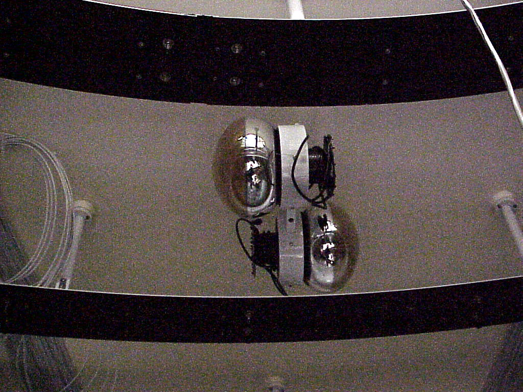
| Another view of veto cluster 2-1. | 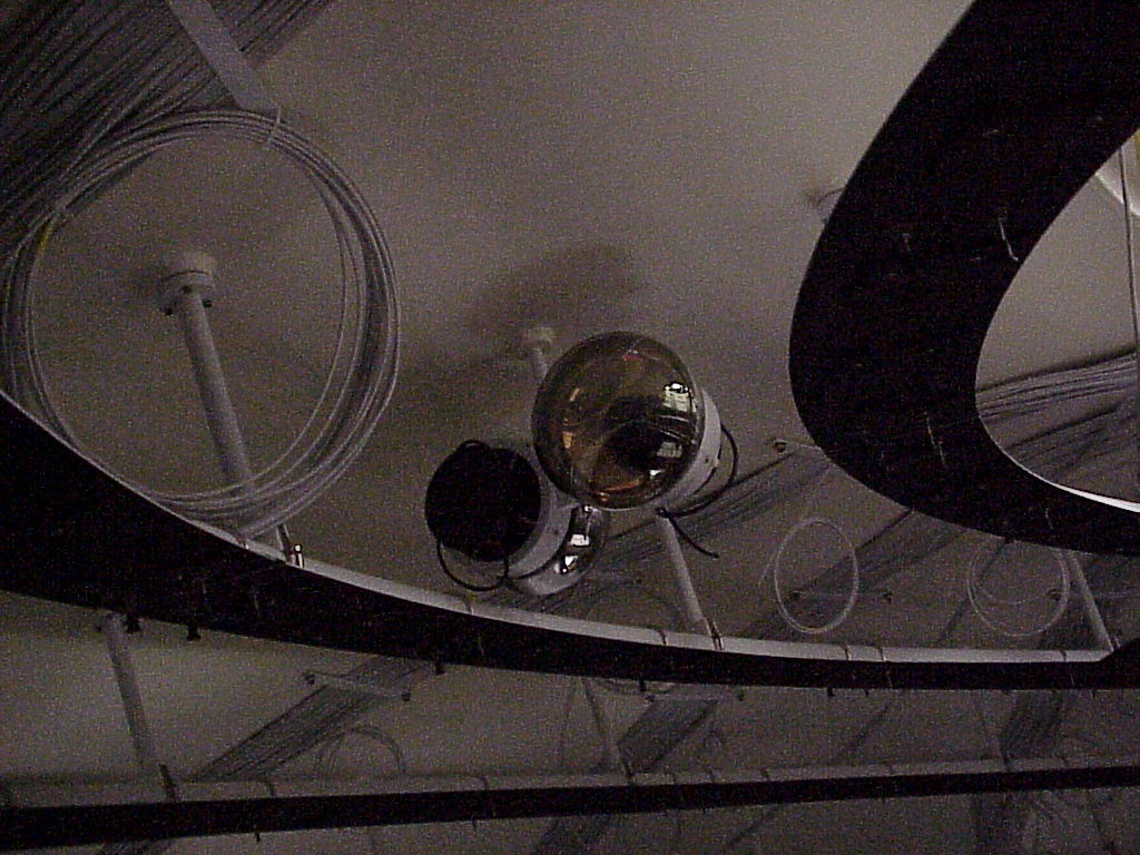
|
| Stan making first splice on veto tube 2-1A. | 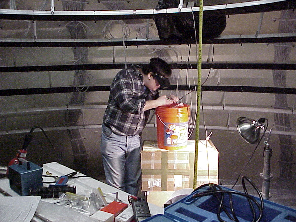
| First splice with oil seal. | 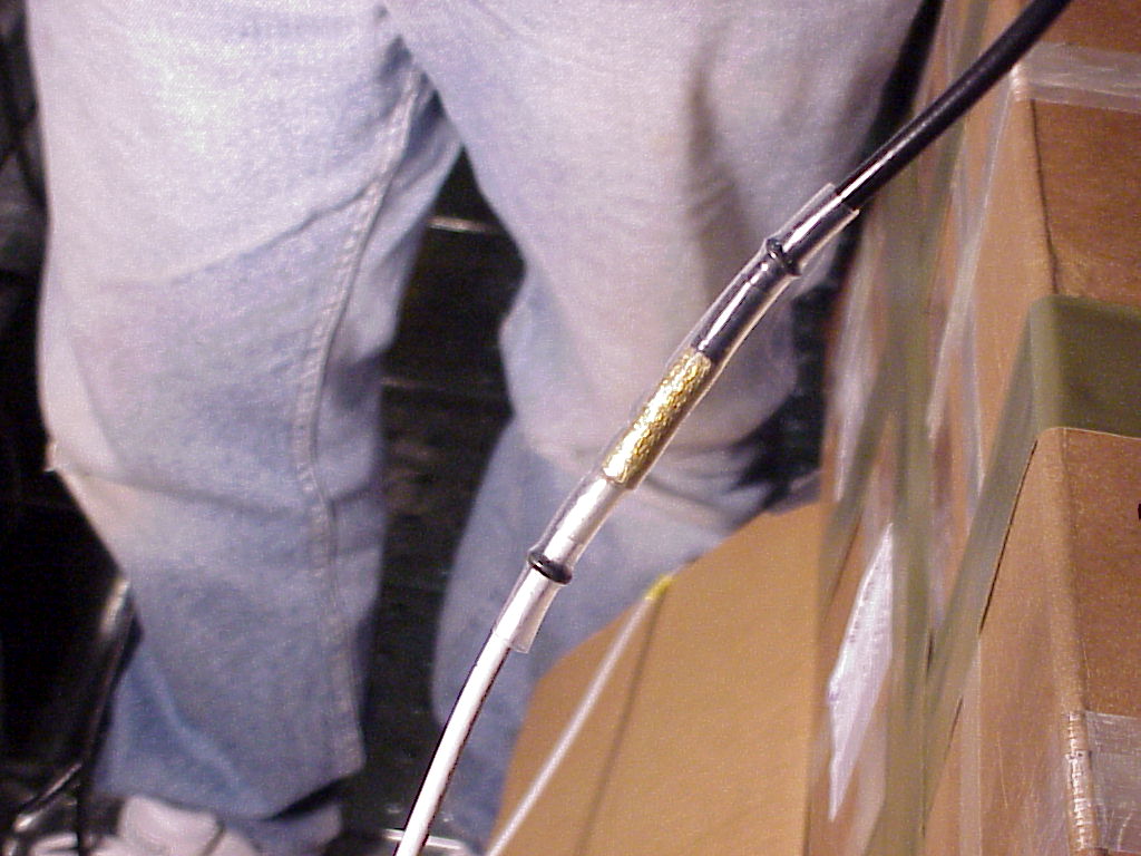
|
| Testing splice 2-1B: before. A NIM-size pulse is split, with one path running directly to the scope (large pulse at left) and the other running down the PMT cable. Before the splice, the reflection from the open end returns to the scope 365 ns later (pulse on right). | 
| Testing splice 2-1B: after. Because the PMT base is back-terminated, with the splice complete the reflection nearly vanishes. (There is a slight impedance mismatch between the long teflon cable and the PVC pigtail on the base.) | 
|
| First row of optical barrier panels (for main PMT row 4) in. (Overlap strips not yet mounted.) | 
| Veto cluster behind OB panel. Click here for a much better picture taken Mar 15. | 
|
Feb 26-Mar 2: More hardware.
| More splicing, on a better table. | 
| The central shaft of the scaffolding. | 
|
| Top lat restored after height adjustment; row 5 of panels started; cables routed through panels. | 
| Bill Groom mounting row 3 panels. | 
|
| Row-3 panel with light-baffled oil port. | 
| Other side of oil port/light baffle. | 
|
| Cable feedthrough. | 
| Cable teasing. | 
|
| Row 3-5 panels. | 
| Rows 3-6,8 showing panel clamps and PMT mounting blocks | 
|
Mar 12-16: Install main (rows 3-6) and veto (row 3) PMT's in upper level.
| Stan waiting for first box of main PMTs. | 
| Bill installing the first main tube, 3-1M. | 
|
| First main tube in place! | 
| Ryan self-portrait in 3-1M. | 
|
| First installed row: main row 3. | 
| Bill Sands. | 
|
| Mike Leung | 
| Rows 3 and 4 installed. | 
|
| Scaffold deck lowered before continuing PMT installation. | 
| Main rows 3-6 in place. | 
|
Mar 17-23: Install main row 7, test installed tubes, remove top scaffold deck.
| Main rows 3-6 in place. | 
| Andrew and Bill splicing row 7. | 
|
| Main rows 3-7 in place. | 
| Main rows 3-7 in place. | 
|
| Andrew and Bill after a long day. | 
| Fernanda, communing. | 
|
| Peter posing. | 
|
Mar 26-30: Install hardware, veto row 4.
| Veto row 4. | 
| Splicing veto row 4. | 
|
| "Boxing ring" tower. | 
| Neil and Peter splicing. | 
|
Apr 2-6: Install main rows 8-10.
| Marching down the sphere. | 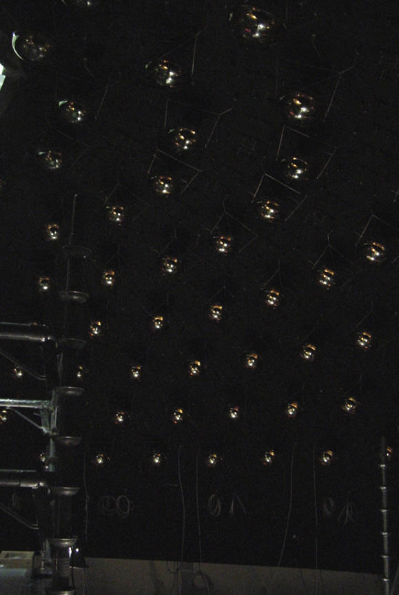
|
| |
| Stan as you've never seen him. | 
| Bill and Hayes lowering scaffolding. | 
|
Apr 9-13: Working on main rows 11, 12.
| QT racks. | 
| Bill Louis prepping panels. | 
|
| Two pictures from the Fermilab photographer. | 
| 
|
Apr 16-20: Splice main rows 11, 12.
Apr 23-27: Install veto row 5, most of main row 13.
Apr 30-May 4: Finish main row 13, install 14. Lead elements reach equator!
| Crossing the equator!. (The row of veto bosses is on the equator.) | 
| View from the equator. | 
|
| Sabina prepping cables for splicing. | 
| Lyuda and Galina prepping cables. | 
|
| Andrew and Sabina | 
| Hayes doing last-minute cleanup before we remove the central tower. | 
|
May 7-11: Install veto row 6, most of main row 15.
May 14-18: Crossing the equator: install rest of main row 15, all of 16, 17.
May 21-25: Install main row 18, most of 19.
May 28-Jun 1: Install rest of main row 19.
Jun 4-8: Install veto row 7. most of main row 20.
| I finally borrowed a tripod! |
| 
| |

| 
|
Jun 11-15: Install rest of main row 20, all of row 21. Return half of scaffold
| Looking down through tophat. | 
| First truckload of scaffolding departing. | 
|
Jun 18-22: Install main rows 22, 23, 24 and veto row 8
Jun 25-29: Install main row 25 and most of 26.
Jul 2-6: Off
Jul 9-13: Install rest of main row 26, all of
main row 27 and veto row 9, most of main row 28 (leaving a gap over the manhole.).
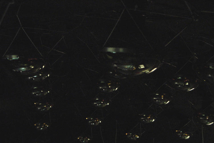
| A beautiful shot of the main and veto tubes. | 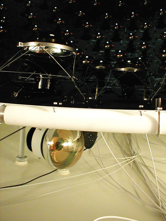
| A sweeping view of the main tube array. | 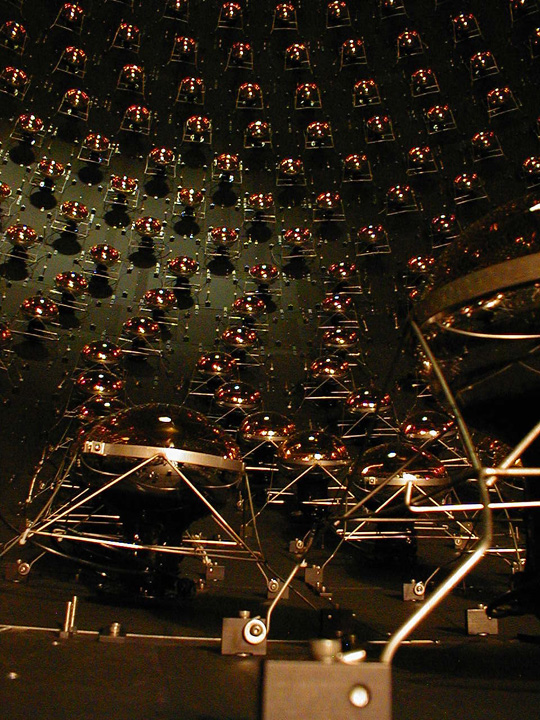
|
| Under the bottom deck. | 
| Ryan and Hayes removing the last scaffolding. | 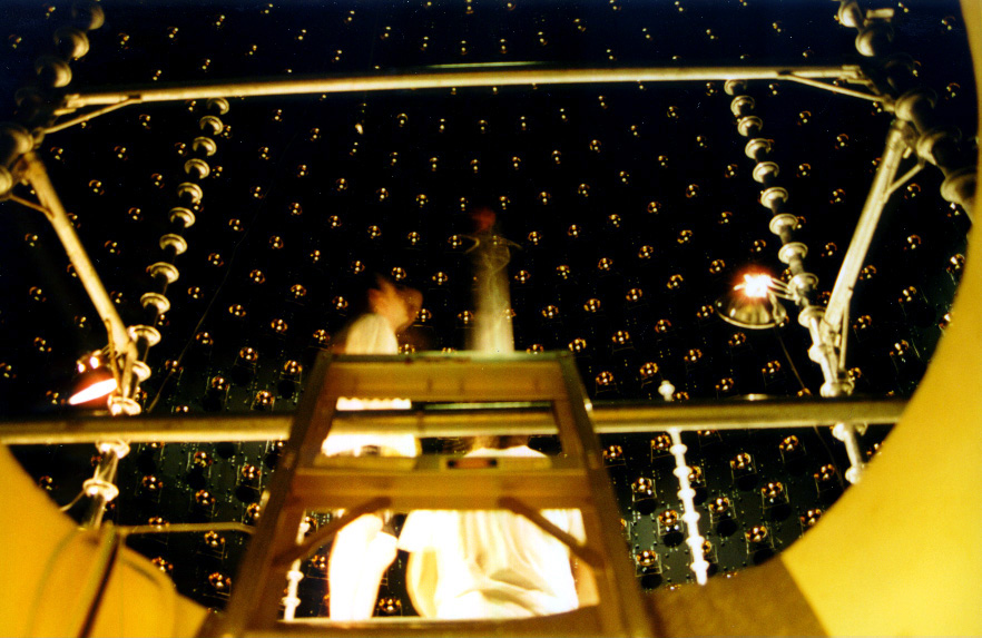
|
| Andrew entering through left-out panels. | 
| Ryan tidying up. | 
|
| Ryan, Peter, and Hayes at the South Pole. | 
| 
|
Jul 16-20: Install main rows 29 and 30 (with gaps for access) and veto row 10. Ready for polar cap endgame.
| A view up through the manhole. No scaffolding! | 
| Looking down through the tophat. |

|
| South polar region, ready for polar cap, which will hold main rows 32 and 33 and veto 11. We left out row 31 to allow walk-around access for installing the cap and the hanging laser flasks. | 
| The exit strategy. Panels and tubes in rows 28-30 were skipped to allow access through the manhole. | 
|
| Frank by the tank lid. | 
| Last truck of scaffolding on its way home. |

|
| A nice one from the pros -- Fred Ullrich/FNAL. | 
|
Aug 20-24: The endgame begins. Install LSU laser flasks.
| Laser flask. | 
| Ryan and Morgan with the catch of the day. | 
|
| Hayes advising Peter. | 
| Fishing out cables to hang flasks. | 
|
| Lowering a laser flask. | 
| Morgan lowering a flask. | 
|
| Laser flasks -- hanging. | 
| Laser flask -- flashing. (Click for larger picture.) | 
|
Sep 4-7: Install North Polar Cap with LSU scintillator cubes. Install South Polar Cap and main row 31.
| North polar cap (NPC) -- bare. | 
| NPC with PMTs and LSU scintillator cubes on rods. Note that the shallowest cube is mounted on a can that blocks light from behind the PMTs. | 
|
| North polar cap (NPC) -- loaded. | 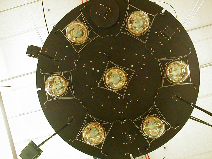
| The endgame crew. Front (l-r): Morgan Wascko, Peter Meyers. Rear (l-r): Richard Imlay, Ryan Patterson, Andrew Bazarko, Bill Sands. (Not present: Hayes Lansford, Myungkee Sung, Aaron McMorris) | 
|
| Ryan preparing the tophat. | 
| ||
| Installing the NPC. Move it across tophat. | 
| With the NPC over the tophat, Ryan, Morgan, Andrew, and Richard deploy the deepest cubes. The 1 m cube's rod is folded down, the 2- and 3-m cubes are lowered on their (common) hanging cable. | 
|
| Lowering into place. | 
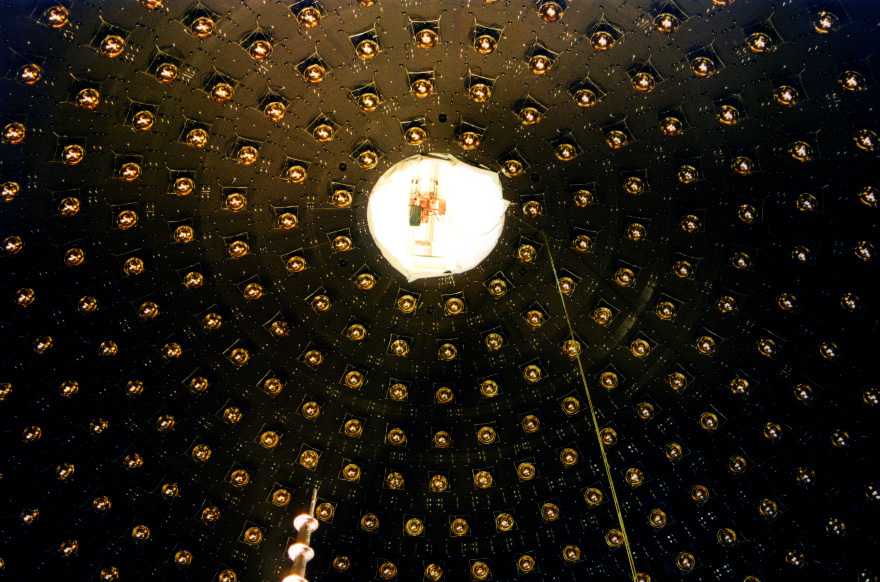
| The North Pole with NPC in place. Note: all flasks and cubes visible in this image. |
|
| Reopening the southern front. The South Polar Cap (SPC) minus its center disk, showing the bottom veto cluster on the concentric fill pipe. | 
| SPC with PMTs in place. | 
|
| Closeup, showing PMT mount and oil baffle on concentric fillpipe. | 
| The South Pole -- complete. The vertical wires tension the hanging laser flasks and scintillator cubes. | 
|
Oct 17-20: Final in-tank installation: top veto cluster and 10 main tubes around manhole, seal top lid.
| North polar cap without and with top veto cluster. | 
| 
| |
| Nice view of hanging flask. | 
| Temporary manhole cover with ventilation. | 
|
| Last look through manhole. |

| View of manhole disk from inside. | 
|
| Bill ready to receive last panel. | 
| Ryan handing in last tube to Bill. | 
|
| Bill installing last tube. | 
| Last panel with tubes. | 
|
| Done! Last panel in place. | 
| ||
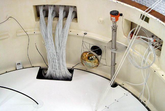
| Top disk in place: completes tank sphere in tophat. Cables penetrating disk are optical fibers from scintillator cubes. | 
| Tophat region, showing 1521st tube. Also visible: cable feedthru, oil-level probe, feedthru panel for N2 and temperature signals. |
|